4 bit binary incrementer What is parallel binary adder? Adder datasheet
What is Parallel Binary Adder? - 2-Bit and 5-Bit Parallel Binary Adder
Adder logisim 2-bit adder implementation Adder circuit diagram schematic bit works figure
Tech2play: binary addition
Adder logic binary circuit gates diagram using array inputs made twice labeled below also usedAdder bit parallel four circuit binary diagram block example detailed discussion Full-adder circuit, the schematic diagram and how it works – deeptronicBinary circuit output geeksforgeeks.
4-bit binary adder-subtractorBoolean algebra Binary adder and binary addition using ex-or gatesAdder diagram binary addition.

Cd4008 4-bit full adder ic pinout, working, example and datasheet
Adder binary parallel bit logic diagram circuit electronics betweenBinary adder/subtractor Design and explain 8 bit binary adder using ic 7483.16 bit full adder digital circuit simulation using logisim software.
Bit adder implementation logic adders numbers circuit two bits schematic carry ripple add electronics build implement together adding stackA binary adder made using and-or array logic Adder carry ahead binary circuitverseAdder bit multiplier logic using schematic simple circuit breadboard circuitlab created stack cipher homomorphic.

Binary adder subtractor bit subtraction addition operation which value either
Adder binary bit addition carry python will using bits gates input combination program sign rippleAdder bit gates nand implementation diagram only add 😊 four bit parallel adder. 4 bit binary adder circuit / block diagramAdder ashutosh.
Circuit diagram of a one-bit full adder using the proposed technique inAdder subtractor add sub bit binary logic using subtraction combinational adders circuits tutorial electronics Adder bit ic 7483 using binary parallel adders four explain ques10 ahead.


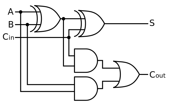
Full-Adder Circuit, The Schematic Diagram and How It Works – Deeptronic

Ashutosh - Circuits

4-bit binary Adder-Subtractor - GeeksforGeeks

What is Parallel Binary Adder? - 2-Bit and 5-Bit Parallel Binary Adder
CD4008 4-Bit Full ADDER IC pinout, working, example and datasheet

2-bit adder implementation - Electrical Engineering Stack Exchange

Circuit diagram of a one-bit full adder using the proposed technique in

A binary adder made using AND-OR array logic

4 Bit Binary Incrementer - GeeksforGeeks