Electronic 12vdc to 120vac inverter circuit diagram Master electronics repair !: voltage converter (12 / ∼220v) with sound 220vdc to 220vac inverter circuit diagram : mz 9679 how to build cheap
voltage - 230V AC to 5V DC converter, lossless - Electrical Engineering
Converter 220v diagram electronics repair master schematic 12v shown Inverter circuit diagram 220vac 12vdc 50w converter power ac vac dc vdc circuits ups cfl supply schematic 12v electronic inverters 220/230v ac to 12v/5v dc regulated power dc converter bridge rectifier
Circuit 12vdc doubler converter
12vdc to 24vdc converter circuit diagram12vdc to 24vdc converter circuit diagram 12vdc 230vac supply voltage sources transformerDc converter 12v 120v inverter convert volt 220v circuits voltage circuitstoday vac convertidor converting corriente.
Dc ac converter circuit 12v 5v power 230v rectifier diagram supply regulated bridge using 220v transformer schematic 1a input ve12v to +/- 20v dc converter Isolated 15 to 1000v dc-dc converter24vdc to 220vac 100 watt, 50hz inverter circuit diagram and working.

Converter dc circuit 12vdc 24vdc 12v 24v schematic simple
Simple dc converter dc 12v to 24v 2a circuit diagramHow to step down 230vac to 24vdc Inverter pcb 220v 220vac layout microtek 220vdc circuits wiring sine 24vdc mz needed 300vChoice4word: 12v dc to 220v ac converter circuit using astable.
12vdc to 24vdc converter circuit diagramInverter 12v 240v circuit 230v inverters electronics tutorial timer Power supplyDc isolated converter circuit 1000v feedback voltage elektropage power schematic electronic load constant kept output will circuits optocoupler.

Dc converter 12v 20v circuit diagram larger click
Circuit supply power transformerless current inrush diagram capacitor ac simple transformer dc capacitive circuits circuite calculation circuitdigest based visitInverter 12v 12vdc converter 24vdc regulated circuits regulator 5v ac dc converter 230v schematic circuit using lossless mode voltage isolated circuitlab created switch12vdc to 220vac 50w converter circuit diagram and instructions.
12v to 230v inverter circuit diagram using 555 timer ic » invertersElectronic diagram 12vdc inverter 120vac circuit 24vdc 230vac 24v regulator graetzRecom 24vdc 12vdc converters.
Dc ac 12v 220v circuit converter inverter diagram simple electronics projects make cool using power choose board electronicshub
Inverter circuit diagram 220vac 24vdc 50hz watt working updated june lastDc converter 24v 12v circuit 2a dc12v diagram simple ic mosfet schematic output circuits step input circuito para using conversor Simple circuit 12v to 120v dc dc converter |audio amplifier schematicConverter circuit 12vdc to 24vdc.
.


voltage - 230V AC to 5V DC converter, lossless - Electrical Engineering

capacitor - Inrush current calculation in capacitive circuite
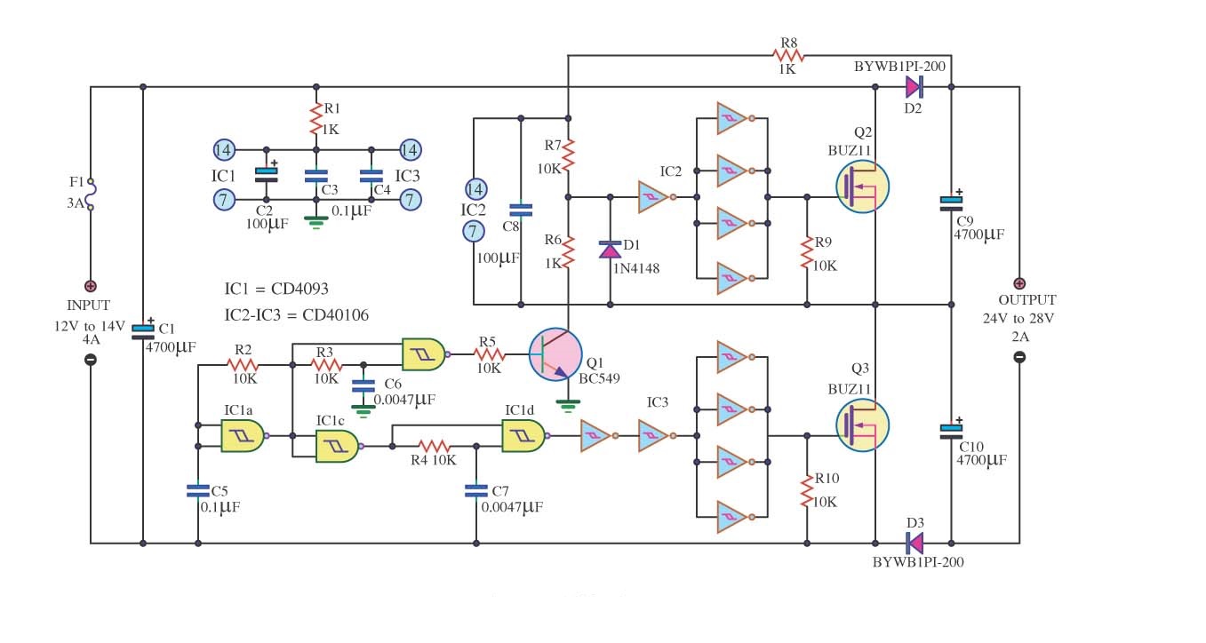
Simple DC Converter DC 12V to 24V 2A Circuit Diagram | Electronic

Choice4Word: 12v DC to 220v AC Converter Circuit Using Astable
Converter circuit 12Vdc to 24Vdc - Simple Schematic Collection
12V to +/- 20V DC Converter - Electronic Circuit
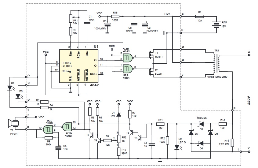
Master Electronics Repair !: VOLTAGE CONVERTER (12 / ∼220V) WITH SOUND

24Vdc to 220Vac 100 Watt, 50Hz Inverter Circuit Diagram and Working