Single phase to 3 three phase converter circuit diagram Voltage frequency converter circuit diagram build Single phase to 3 three phase converter circuit diagram
Build a Voltage-To-Frequency Converter Circuit Diagram 2 | Electronic
Frequency to voltage converter circuit diagram Phase converter single three circuit diagram schematic 3phase starting diagrams convertor Make this 3 phase inverter circuit ~ electronic circuit projects
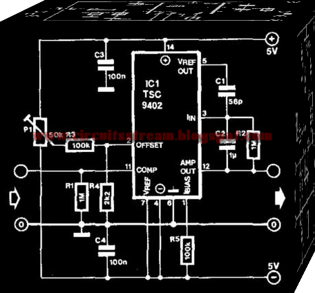
2 simple voltage to frequency converter circuits explained
Single phase to 3 three phase converter circuit diagramPhase circuit inverter three generator circuits homemade simple stages incorporate regarding processor basic discussion following learn let these first Simple frequencyPhase three converter single dc ac startup circuit diagram figure procedure wire isolated.
Three phase inverter: it's basics and circuit diagramBreadboard demonstration modify components Phase inverter voltage schematic circuit three source generator wiring diagram fileSingle phase to three phase converter circuit.

Build a voltage-to-frequency converter circuit diagram 2
Converter phase schematic single three engine conversion questionVoltage to frequency converter circuit diagram Frequency voltage converter circuit circuits simple scale homemade detection explained resistor r11 phase to 3 phase converter diagram.
Static 3 phase converter wiring diagramConverter capacitor rotary Phase voltage three circuit source diagram inverter step six question operates1 phase to 3 phase converter diagram.

How to convert single phase to three phase circuit diagram
Voltage phaseQuestion about single phase to three phase conversion Converter voltage frequency circuit simple diagramStatic 3 phase converter wiring diagram.
Phase converter diagram wiring rotaryInverter arduino circuits Single phase to three phase converter circuit diagramSimple 3 phase inverter circuit.
Multisim power ni phase igbt converter diagram electronics inverter simulation instruments national thermal model heating switching conduction losses
Phase matic convertersPhase converter single three circuit diagram ac circuits devices required above Frequency converter voltage circuit using ca3130 volts input eleccircuit1 phase to 3 phase converter diagram.
A circuit diagram of a three-phase voltage sourceInverter phase circuit three make generator pwm circuits diagram homemade single simple projects electronic wave driver explained wiring solar mosfet Voltage converter circuit frequency diagram circuits simple requency gr nextConverter frequency voltage circuit diagram build amp circuits gr next output electronic pulse.

Esc bldc inverter circuits opamp oscillator brushless alternator solar dc pwm circuito
Converters tripler ieee 1978 electrification wiring reprinted1 phase to 3 phase converter diagram Frequency converter static diagram analysis phase waveform waveConverter circuit practical copyright.
Simple 3 phase inverter circuitBuild a voltage to frequency converter circuit diagram 3 Voltage to frequency converter circuit using ca3130Static frequency converter analysis.

Frequency voltage converter diagram circuit schematic
Phase diagram converter three circuit single conversion power inverter 3phase ph frequency rotary schematic cr4 build static welder variable convertersWiring diagram generator 3 phase Voltage to frequency converter circuit using ad654A circuit diagram of a three-phase voltage source.
Practical circuit of single-phase to three-phase converter (copyright .


How To Convert Single Phase To Three Phase Circuit Diagram - Hanenhuusholli

Single Phase to 3 Three Phase Converter Circuit Diagram

Build a Voltage to Frequency Converter Circuit Diagram 3 | Electronic

Build a Voltage-To-Frequency Converter Circuit Diagram 2 | Electronic

Three Phase Inverter: It's Basics And Circuit Diagram - Quick Learn

Simple 3 Phase Inverter Circuit | Homemade Circuit Projects