Loop current ma 20ma loops source science fig1 hackaday automation basic inc building Thermocouple voltage circuits opamp Voltage to current source 4-20 ma – electronic circuits – schematic
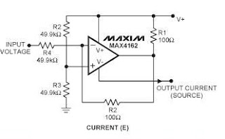
power electronics - How the does this circuit source 4-20mA
Electronic device and electronic circuit: isolate 4-20ma to voltage circuit 4 to 20ma wiring diagram Power electronics
20ma circuit output source lm358 using current resistor electronics mosfet transistor does use flow network based stack
20ma circuitlab20ma connections 4-20 ma source circuit20ma 10v analog signal over why loop current use circuit typical process preferrably control send location figure.
Why we preferrably use 4-20ma over 0-10v & 0-20ma as a analog signalSource circuit ma 20ma Operational amplifier3v 20ma amplifier uc explain.

How/can i plug a 3 wire 4-20ma current sink probe into a 2 wire 4-20ma
Source circuit ma 20ma current amp resistor4 to 20 ma current loop output signal 4 20ma to 0 10v converter circuit diagram20ma esp8266 adc signal analog connecting.
4-20 ma source circuitOp amp 20ma signal output convert circuit ma loop current vdc resistor voltage 5vdc ohm 250 resistance volt change will sensor volts20ma 10v circuit converter diagram schematic convert input microcontroller shunt resistor scatter ma plot bright colors dark figure across.

20ma circuit schematic amps loop circuitlab
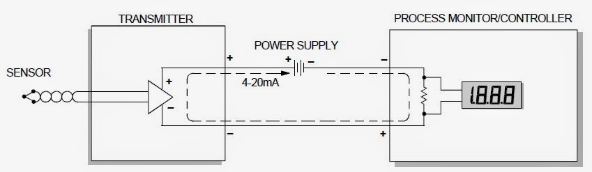
The 4-20 ma current loop20ma isolate output device requires compliance .
.


analog - Connecting 4-20mA signal to esp8266 ADC circuit - Electrical
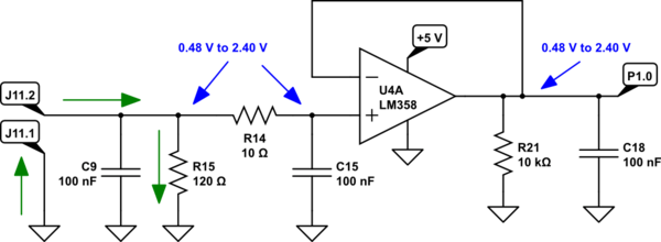
op amp - How does this circuit read 4-20mA current loop input through
4-20 mA source circuit | Electronic Circuit Directory

Voltage to Current Source 4-20 mA – Electronic Circuits – Schematic

4-20 mA source circuit | Electronic Circuit Directory

4 to 20 mA Current Loop Output Signal - SensorsONE

power electronics - How the does this circuit source 4-20mA

The 4-20 MA Current Loop | Hackaday
Why We Preferrably Use 4-20mA Over 0-10V & 0-20mA As A Analog Signal