Adder circuit construction binary circuits qiskit sourav gupta Adder logic half implementation Adder carry ripple adders calculate eec
11+ 4 Bit Adder Circuit Diagram | Robhosking Diagram
Adder circuit diagram using carry truth table construction schematic 4bit shown ttl chip ahead feature below look Let's learn computing: 4 bit adder/subtractor circuit Adder bit binary circuitverse
Adder bit circuit half make logic diagram comparator gates first electronics questions cout second there only solved puzzle connecting which
Adder circuit implementation novelDigital logic Adder alu nor nandAdder bit logisim using circuit cs lab1 cornell labs courses edu build create re ta sub ask.
Adder subtractor bit circuit add sub overflow complement logic detection carry designing control zero addition line questions digital computerFull adder circuit: theory, truth table & construction 10+ adder circuit diagramFull-adder circuit, the schematic diagram and how it works – deeptronic.

Adder circuit diagram geeksforgeeks bit subtractor binary source
Adder bit circuit adders gate sum expressions implementFull adder circuit: theory, truth table & construction 11+ 4 bit adder circuit diagramCircuit adder bit diagram logic computing learn let.
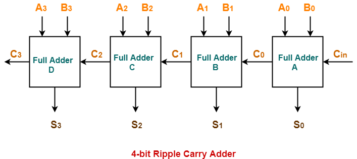
11+ 4 bit adder circuit diagram4 bit full adder circuit, truth table and symbol. implement 4 bit Boolean algebraAdder ripple circuitverse.

Adder carry ahead bit look circuit diagram gate ripple delay logic applications truth table count find sponsored links
Adder bcdAdder bit circuitverse Carry look-ahead adderAdder bit gates nand implementation diagram only add.
Adder bit circuit subtractor ripple carry logic diagram using project only digital its computing learn let build single indie electronicsCs 3410 spring 2018 lab 1 Adder logic bit four diagram half boolean two function simple adders answer so nowAdder circuit diagram schematic bit works figure.
Let's learn computing: 4 bit adder circuit
11+ 4 bit adder circuit diagramThe answer is 42!!: four bit full adder tutorial Logic gates.
.


10+ Adder Circuit Diagram | Robhosking Diagram

11+ 4 Bit Adder Circuit Diagram | Robhosking Diagram

11+ 4 Bit Adder Circuit Diagram | Robhosking Diagram

digital logic - Designing a 4-bit adder-subtractor circuit - Electrical

11+ 4 Bit Adder Circuit Diagram | Robhosking Diagram

logic gates - How to make 2 bit or more half adder circuit - Electrical

CS 3410 Spring 2018 Lab 1

Adder - Classifications, Construction, How it Works and Applications