Are the mux with 3 inputs and and with 2 inputs gate the same Mux using diagram block only 16 four logic digital slideplayer courtesy there common Crossword puzzle clip mux vector inputs illustrations gate same then if x0
VIRTUAL LAB - ECE18R369 DIGITAL VLSI DESIGN
16:1 mux : vlsi n eda 2 input mux Multiplexer mux demultiplexer d0 d3 d2 d1 ppt
Digital logic
Mux inputsMux inputs figuring Mux input eight figure used solved has four chegg logic implement function questions shows problem beenDigital logic.
8x1 mux logic diagram : using 8 1 multiplexers to implement logicalMultiplexers: not so simple Multiplexer truth table circuitProblems on mux / finding the inputs to the given multiplexer / how to.

A cyberphysics page
Mux functional diagram logic circuits combinational other ppt powerpoint presentationSolved figure 3 shows how an eight-input mux can be used to Mux multiplexer 8x1 diagram logic table schematic using truth input 16 vlsi 2x1 muxes symbol figure structure eda elchoCyberphysics input multiplexers.
Mux inputs figuringInput multiplexer two logic combinational circuits other ppt powerpoint presentation mux 2-to-1 mux using if-then-else statement in vhdl – buzztechA cyberphysics page.

Mux inverting multiplexers e2e ti introduces
Cyberphysics multiplexer considerXor mux implement 4x1 mux logic diagram / solved: write vhdl programs for a 4x1Design xor gate using 2:1 mux.
Verilog code for 2:1 multiplexer (mux)Multiplexers and de-multiplexers » examradar Mux multiplexer verilog 2x1 code technobyteMux using nand gate input gates multiplexer 2x1 implementation figure logic implemented.
![2 to 1 Multiplexer Circuit : With Truth Table [TRY IT] - YouTube](https://i.ytimg.com/vi/K9UlJrSFWD8/maxresdefault.jpg)
Mux constructed
8x1 mux logic diagram / multiplexer 8 to 1 logic diagram 2002 chevy z71Mux multisim Mux input combinationalMux multiplexer multiplexers enable examradar output logic disabled.
Multiplexer mux 2x1 electrical4u wiringAre the mux with 3 inputs and and with 2 inputs gate the same 8x1 mux multiplexer 4x1 logic implementation implement multiplexers logical 2x1 hardwareMux inputs gate same when truth seen table also.

2 to 1 multiplexer circuit : with truth table [try it]
2 input mux2-input gates using 2:1 mux Input mux multisimDigital logic.
Multiplexer logic mux 4x1 vhdl demultiplexer multiplexers verilog solved powerpoint implement waysMux vhdl using diagram block else statement then if Virtual lab.


A Cyberphysics Page

digital logic - 4 To 1 MUX - Figuring out the inputs - Electrical

Are the MUX with 3 inputs and AND with 2 inputs gate the same

8X1 Mux Logic Diagram / Multiplexer 8 To 1 Logic Diagram 2002 Chevy Z71

16:1 mux : VLSI n EDA

4X1 Mux Logic Diagram / Solved: Write VHDL Programs For A 4x1
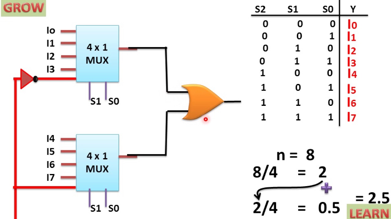
8X1 Mux Logic Diagram : Using 8 1 Multiplexers To Implement Logical